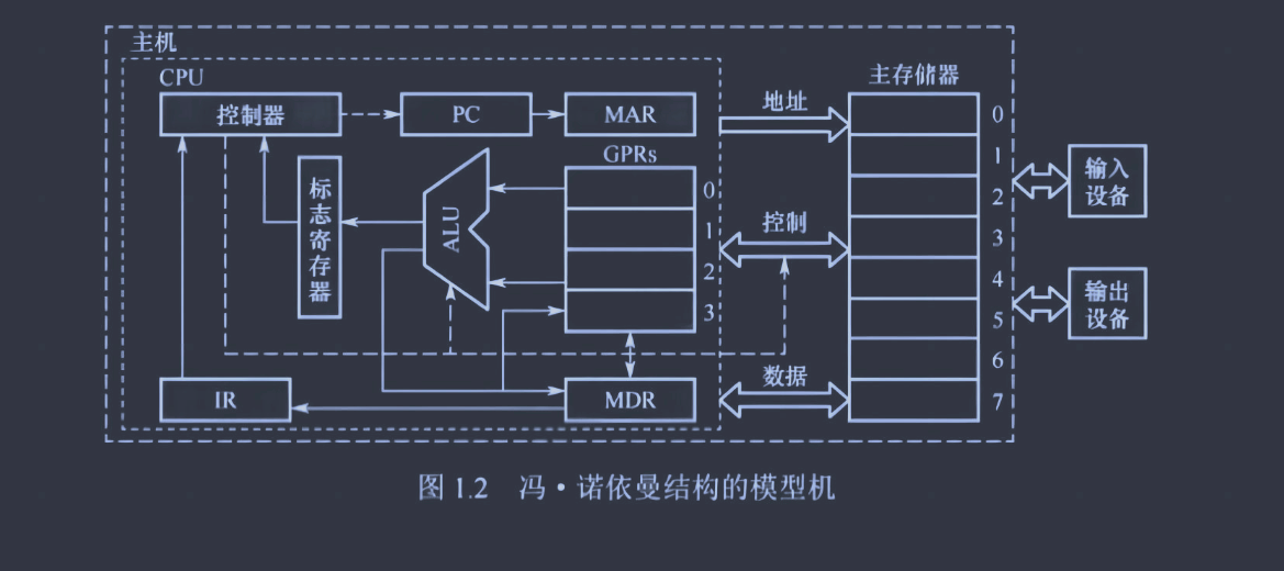
An electronic digital computer with these components:
Processor unit: arithmetic unit and processor registers
control unit: instruction register(IR) and program counter(PC)
Memeory
External mass storage
Input and Output mechanisms
Instructions and data are stored in memory with equal status.
Instructions is composed of Opcode and ddress code, the address code is used to point Operand.
The term “von Neumann architecture” has evolved to refer to any stored-program computer in which an instruction fetch and a data operation cannot occur at the same time (since they share a common bus)
Function call is running in user mode, using the user source, and there is no need for privilege switching and context restoring.
System call is the request from user mode to higher privilege mode, for getting into system to use kernel source such as I/O device, network interface.
System call
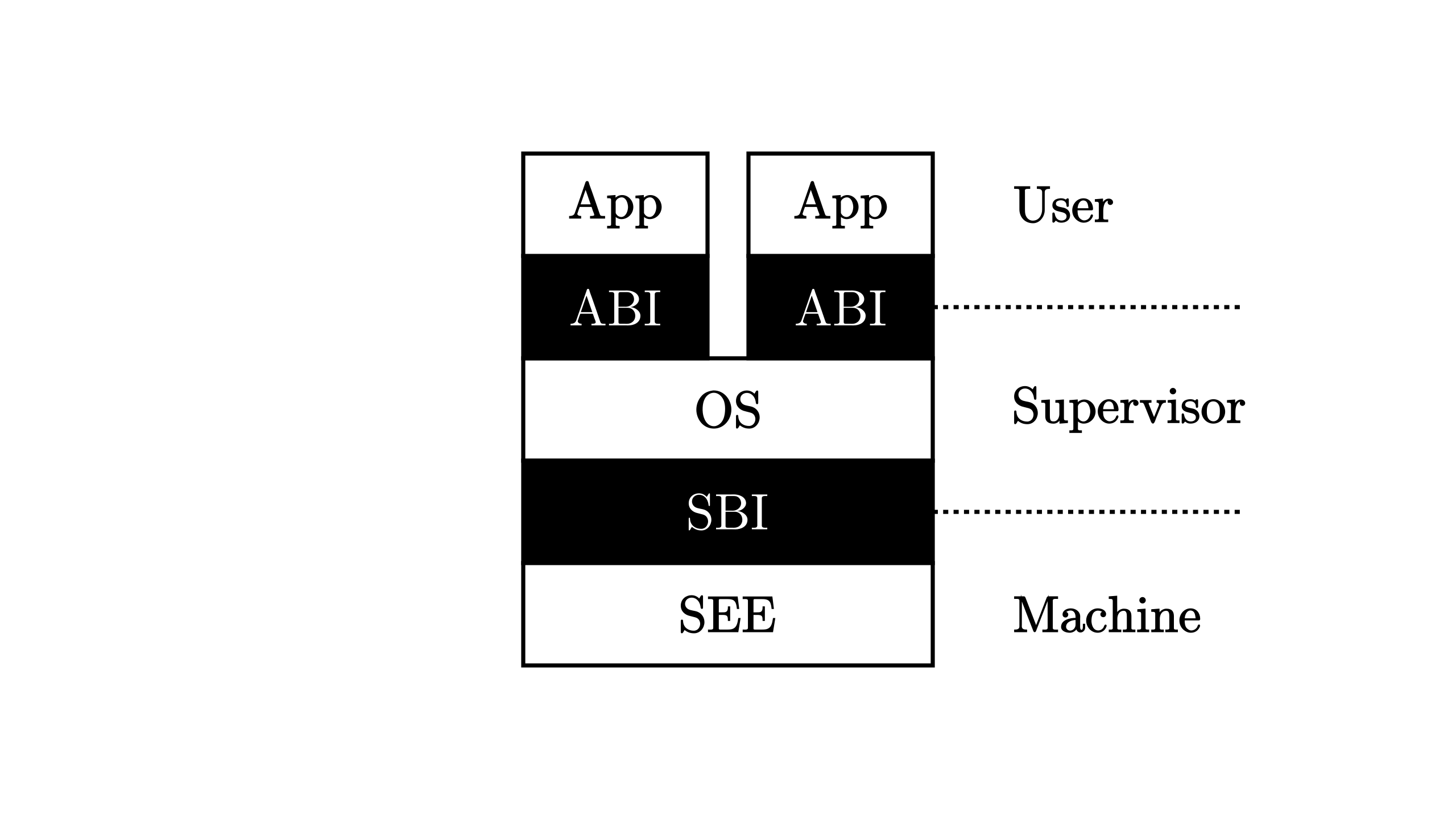
System call is the ABI(Application Binary Interface), which provide interface for U mode to use OS source. The follow is the process of system call:
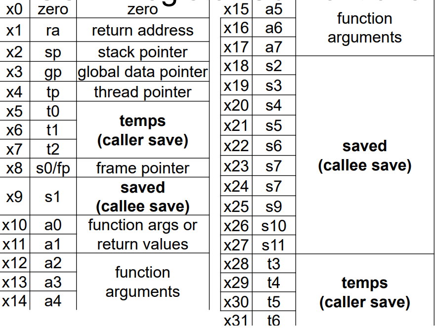
The user program prepares for system call by loading the system call number and the arguments that needed in predefined registers(a7: system call number, a0~a6: Hold arguments of system call, a0 also hold the return value from the system call)
After that, user program issue the ecall instruction. After the ecall executed, a trap occurs, and the trap context switch performs. The CPU transfers control to the operating system’s trap handler. The trap handler use the sscause and system call number in a7 to execute requested system call. Once the system call is completed, the return value (if any) is placed in register a0.
Finally, restore user context to return user mode.
1
2
3
4
5
6
7
8
9
10
11
12
13
14
15
16
17
18
.section .data
message:
    .asciz "Hello, World!\n"

.section .text
.globl _start
_start:
    # System call to write
    li a7, 64          # Load system call number for 'write' (64) into a7
    li a0, 1           # File descriptor 1 (stdout) into a0
    la a1, message     # Load address of message into a1
    li a2, 14          # Message length (14 bytes) into a2
    ecall              # Issue the system call

    # System call to exit
    li a7, 93          # Load system call number for 'exit' (93) into a7
    li a0, 0           # Exit code 0 into a0
    ecall              # Issue the system call
ASIDE: WHY SYSTEM CALLS LOOK LIKE PROCEDURE CALLS
You may wonder why a call to a system call, such as open() or read(), looks exactly like a typical procedure call in C; that is, if it looks just like a procedure call, how does the system know it’s a system call, and do all the right stuff? The simple reason: it is a procedure call, but hidden inside that procedure call is the famous trap instruction. More specifically, when you call open() (for example), you are executing a procedure call into the C library. Therein, whether for open() or any of the other system calls provided, the library uses an agreed-upon calling convention with the kernel to put the arguments to open in well-known locations (e.g., on the stack, or in specific registers), puts the system-call number into a well-known location as well (again, onto the stack or a register), and then executes the aforementioned trap instruction. The code in the library after the trap unpacks return values and returns control to the program that issued the system call. Thus, the parts of the C library that make system calls are hand-coded in assembly, as they need to carefully follow convention in order to process arguments and return values correctly, as well as execute the hardware-specific trap instruction. And now you know why you personally don’t have to write assembly code to trap into an OS; somebody has already written that assembly for you.
Trap Management
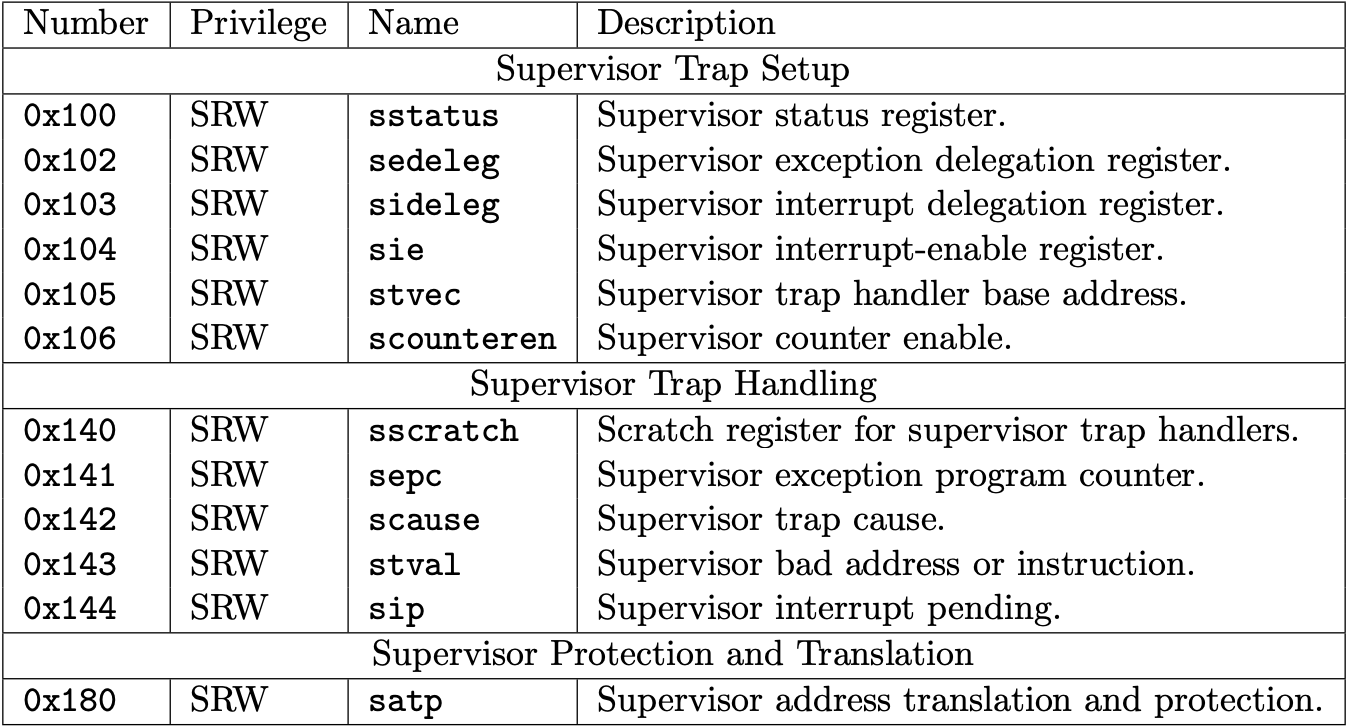
When user program issues the ecall instruction, it trigger the trap execution to switch the processor from user mode to supervisor mode. Then the first step is to find the trap handler entry address to jump to. To do this, the kernel set the trap table at boot time.
In rCore, at boot time, trap entry address is set by
1
2
3
4
5
6
7
8
9
/// initialize CSR `stvec` as the entry of `__alltraps` pubfninit() { extern"C" { fn__alltraps(); } unsafe { stvec::write(__alltraps asusize, TrapMode::Direct); } }
There is only a single trap entry _alltraps. All traps get into _alltraps to do trap context save and load and run different functionality base on what exception was(sscause).
*sstatus* used to back to the mode before trap.
*spec* save the last instruction before trap, which used to continue user program(PC is set sepc) after issued *sret* return user mode.
.align 2 __alltraps: csrrw sp, sscratch, sp # now sp->kernel stack, sscratch->user stack # allocate a TrapContext on kernel stack addi sp, sp, -34*8 # save general-purpose registers sd x1, 1*8(sp) # skip sp(x2), we will save it later sd x3, 3*8(sp) # skip tp(x4), application does not use it # save x5~x31 .set n, 5 .rept 27 SAVE_GP %n .set n, n+1 .endr # we can use t0/t1/t2 freely, because they were saved on kernel stack csrr t0, sstatus csrr t1, sepc sd t0, 32*8(sp) sd t1, 33*8(sp) # read user stack from sscratch and save it on the kernel stack csrr t2, sscratch sd t2, 2*8(sp) # set input argument of trap_handler(cx: &mut TrapContext) mv a0, sp call trap_handler
It is a firmware that provide the necessary instruction for the computer to perform basic functions such as hardware initialization.
Functions of the BIOS
Power-On Self-Test (POST): When you turn on your computer, the BIOS performs a POST to check that all the necessary hardware components (like memory, keyboard, and storage devices) are functioning correctly.
Bootloader Execution: After the POST, the BIOS looks for a bootable device (like a hard drive, SSD, USB drive, or CD/DVD) and loads the bootloader from the bootable device into memory. The bootloader then takes over to load the operating system kernel.
Hardware Initialization: The BIOS initializes and configures hardware components, setting up basic operational parameters. This includes setting up the CPU, memory, and peripherals such as disk drives and video cards.
BIOS Setup Utility: The BIOS includes a setup utility that users can access to configure hardware settings, such as system time and date, boot sequence, and hardware parameters.
BIOS Services: The BIOS provides low-level routines that operating systems and programs can use to interact with hardware. These routines offer a standardized way for software to communicate with hardware devices without needing to know the details of the hardware.
BIOS interrupt
It refer to invoke routines provided by the BIOS to the x86-based computer. It allows the CPU to switch from executing the current program to the routine provided by the BIOS. Calling BIOS Interrupts:
To invoke a BIOS interrupt, software sets up registers with specific values, including the interrupt number (represented as an index into the IVT). Then, the software triggers the interrupt using the INT instruction, which causes the CPU to transfer control to the corresponding ISR in the BIOS. Purpose and Usage:
BIOS interrupts are used to perform low-level operations that interact directly with hardware, such as disk I/O, keyboard input, video display, system timer control, and system shutdown/restart functions.
They provide a standardized interface for software running in real mode to access these hardware functions without needing to know specific hardware details.
Example of BIOS interrupt
INT 13h: Provides disk services, such as reading and writing sectors from/to disk drives INT 15h: Provides system services, including memory allocation, system configuration query, and power management functions.
Bootloader
Bootloader is a program to load the operator system kernel into memory.
Functions of a Bootloader
Power-On Self-Test (POST): When you turn on your computer, the Basic Input/Output System (BIOS) or the Unified Extensible Firmware Interface (UEFI) performs a POST to check hardware components’ functionality.
Boot Device Detection: After the POST, the BIOS/UEFI searches for a bootable device, such as a hard drive, SSD, USB drive, or CD/DVD, based on the boot order specified in BIOS/UEFI settings.
Loading the Bootloader: Once a bootable device is detected, the BIOS/UEFI loads the initial bootloader program stored in a specific location on that device (e.g., the Master Boot Record or EFI System Partition).
Bootloader Execution: The bootloader program takes control, initializes hardware (if necessary), and allows the user to select which operating system or kernel to load if multiple options are available (e.g., dual-boot systems).
Loading the Kernel: The main task of the bootloader is to load the operating system kernel into memory. It reads the kernel file from the boot device and transfers control to the kernel, passing any necessary parameters.
Transition to Operating System: Once the kernel is loaded and initialized, the operating system takes over and continues the boot process. The OS then loads necessary drivers, initializes system services, and presents the user with a login screen or desktop environment.
Load kernel process
LBA
LBA is commonly used in BIOS (Basic Input/Output System) and operating systems to access data on hard drives, solid-state drives (SSDs), and other storage devices. When reading or writing data to a disk using LBA, the operating system or application specifies the LBA address along with other parameters (such as the number of sectors to read/write and the buffer address).
How to read a sector
Prepare Registers:
mov $0x42, %ah sets AH to 0x42 to indicate the Extended Read function.
mov %sp, %si sets SI to point to the stack pointer, which will be used as the pointer to the data packet.
Push [[Data packet]] onto the Stack:
Push the packet size (16 bytes).
Push the number of sectors to read (1 sector).
Push the buffer offset (0), which is the offset within the segment where data should be read into.
Push the buffer segment (ES), which is the segment where data should be read into.
Push the LBA address in three parts (high part, mid part, low part).
Call BIOS Interrupt:
int $0x13 calls the BIOS interrupt to perform the Extended Read operation using the data packet.